- Posts: 24
- Thank you received: 0

Cycle Counter for Bilge Pump
- mgraham
-
 Topic Author
- Offline
- Junior Member
-

Less
More
7 years 8 months ago #5039
by mgraham
Cycle Counter for Bilge Pump was created by mgraham
I have become convinced of the utility of a simple cycle counter on the bilge pump on my IP 44. We have had, twice, leaks that would cause the bilge pump to cycle perhaps twice an hour, which was not noticeable until the float switch failed. The it was the boot stripe that provided the warning. (the float switch on the high water alarm also failed. (Maintenance has improved, one fail happens, but I should have caught the high water alarm in routine maintenance).
I have bought a simple counter made for this purpose, which shows the positive wire hooked to the negative side of the float switch (actually not negative, but the side which is not hot unless the switch is activated). and the negative side of the counter is wired to the negative side of the batteries. That is a long wire run, and appears to be unneccessary, but I would like to hear from others.
My idea is to hook to positive side to the red light that comes on at the battery selector panel when the bilge pump is activated, and the negative side to the negative side of the battery. Can anyone think of a problem with this?
Please Log in or Create an account to join the conversation.
- douglasbronson
-

- Offline
- New Member
-

Less
More
- Posts: 9
- Thank you received: 1
7 years 8 months ago - 7 years 8 months ago #5044
by douglasbronson
Replied by douglasbronson on topic Cycle Counter for Bilge Pump
hi mgraham
See that no one has piped in yet, so I'll give it a shot.
I don't know who's counter system you are using, but I installed a AquaAlarm Bilge control and counter.
AquaAlarm Pump Counter with 3 Way Pump Switch
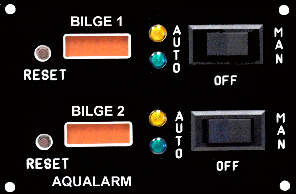
Pretty easy to install. Just moved the wires from the factory switches to the AquaAlarm Panel.
I see no reason why, with your counter, you can't just wire it into the Run LED. However, I would run the wires to the switch and ground buss bar, instead of splicing them into the LED pigtail. Lot easier and neater.
Hope this helps.
See that no one has piped in yet, so I'll give it a shot.
I don't know who's counter system you are using, but I installed a AquaAlarm Bilge control and counter.
AquaAlarm Pump Counter with 3 Way Pump Switch
Pretty easy to install. Just moved the wires from the factory switches to the AquaAlarm Panel.
I see no reason why, with your counter, you can't just wire it into the Run LED. However, I would run the wires to the switch and ground buss bar, instead of splicing them into the LED pigtail. Lot easier and neater.
Hope this helps.
Last edit: 7 years 8 months ago by douglasbronson.
Please Log in or Create an account to join the conversation.
- mgraham
-
Topic Author
- Offline
- Junior Member
-
Less
More
- Posts: 24
- Thank you received: 0
7 years 8 months ago - 7 years 8 months ago #5049
by mgraham
Replied by mgraham on topic Cycle Counter for Bilge Pump
We were thinking the same. But I bought the counter only. When you say running to the switch, do you mean the float switch, or an inline relay since there is an on/off, a manual switch, and then float switch activation. I can run to float switch, it is a threading hassle to do a neat job. But I get the reliability.
Last edit: 7 years 8 months ago by mgraham.
Please Log in or Create an account to join the conversation.
- douglasbronson
-
- Offline
- New Member
-
Less
More
- Posts: 9
- Thank you received: 1
7 years 8 months ago #5050
by douglasbronson
Replied by douglasbronson on topic Cycle Counter for Bilge Pump
I mean the Auto/Off/Run toggle switch.
You want to put the Positive lead off the counter to the RUN terminal. The ground just goes to a convenient ground buss.
If all else fails, follow the Run LED leads, and attach the Counter leads to the same place. It should be apparent which one is the ground lead (black or yellow).
This is assuming that the new counter is in the same general location as the Auto/Off/Run switch.
Please Log in or Create an account to join the conversation.
- douglasbronson
-
- Offline
- New Member
-
Less
More
- Posts: 9
- Thank you received: 1
7 years 8 months ago #5051
by douglasbronson
Replied by douglasbronson on topic Cycle Counter for Bilge Pump
Hold on a sec.
Do you have two switches, a master On/Off and a manual switch?
If so, hook the positive lead to the load side of the Manual switch.
Ground, once again goes to any convenient ground buss.
Do you have two switches, a master On/Off and a manual switch?
If so, hook the positive lead to the load side of the Manual switch.
Ground, once again goes to any convenient ground buss.
Please Log in or Create an account to join the conversation.
- mgraham
-
Topic Author
- Offline
- Junior Member
-
Less
More
- Posts: 24
- Thank you received: 0
7 years 8 months ago #5052
by mgraham
Replied by mgraham on topic Cycle Counter for Bilge Pump
Your intuition exceeded my ability to describe. Yes. Auto/Run/off. So the Run terminal gets power in two instances. When momentarily pressed to run, and when the float switch kicks it on?
Please Log in or Create an account to join the conversation.
- douglasbronson
-
- Offline
- New Member
-
Less
More
- Posts: 9
- Thank you received: 1
7 years 8 months ago #5053
by douglasbronson
Replied by douglasbronson on topic Cycle Counter for Bilge Pump
You got it.
Here is a simplified wiring diagram of a common bilge pump set up.
The output of both switches (Auto/Off/Run switch and Float switch) are connected to the pump's positive wire/terminal.
So if either one is activated, the other will see power too. Hence the reason the "RUN" light works.
Here is a simplified wiring diagram of a common bilge pump set up.
The output of both switches (Auto/Off/Run switch and Float switch) are connected to the pump's positive wire/terminal.
So if either one is activated, the other will see power too. Hence the reason the "RUN" light works.
The following user(s) said Thank You: mgraham
Please Log in or Create an account to join the conversation.
- mgraham
-
Topic Author
- Offline
- Junior Member
-
Less
More
- Posts: 24
- Thank you received: 0
7 years 8 months ago #5054
by mgraham
Replied by mgraham on topic Cycle Counter for Bilge Pump
Perfect sense when I look at the wiring diagram. Thank you so much for the insight.
Please Log in or Create an account to join the conversation.
Time to create page: 0.405 seconds
We have 736 guests and one member online
Disclaimer
Island Packet and Island Packet Yachts are registered trademarks of IPY (Island Packet Yachts, Inc.). IPYOA and The Island Packet Yacht Owners Association, have no affiliation with IPY, the Island Packet Yacht Company. Throughout our IPYOA Facebook Group and on this IPYOA.com website the terms Island Packet and Island Packet Yachts are used for identification purposes only. This use is FAIR USE and NOMINATIVE. We are NOT a yacht manufacturer we are a yacht owners group.
Sincerely,
The International IPYOA administration team.